
Rotation Specifications#
This section descibes special input for controlling boundary condition implementation of vector equations in 3D problems. For 2D problems, the information in this section of the Goma input file is not read or used. It is also optional in 3D problems when none of the boundary conditions are rotated (see discussion below). However, these specifications are mandatory in all 3D problems which require equation rotation at the boundaries (e.g. PLANE, KINEMATIC, VELO_NORMAL), a condition especially prevalent in free-surface problems. The goal of this input section is to specify the exact implementation of the equations at any boundary with rotated conditions (called rotated boundaries throughout this discussion). But first, consider the necessary background.
Rotation of Vector Equations : The fluid momentum and psuedo-solid or Lagrangian solid momentum equations are vector equations (i.e., they have x, y, and z components). The boundary conditions applied to these equations can either be vector conditions (applying in the x, y, and z directions) or scalar conditions (a single function of the solution and x, y, and z). Scalar conditions applied to vector equations represent a special challenge, because it is often unclear which of the vector equations should be replaced by the scalar conditions. For many scalar conditions, e.g. Dirichlet conditions, the user specifies which component of the momentum equation gets replaced by the scalar condition; however, not replacing all the components of the vector equation at a boundary results in applying a shear-stress-free or normal-stress-free condition there (because the BOUNDARY term of the equations needs to be computed or else the normal traction is implicitly zero).
In some cases, a better way to apply a scalar condition is to use it to replace the normal or tangential contribution of the vector equations, while retaining the other portions of the equation (e.g., a no penetration condition could constrain the normal component of velocity but still allow the stress along the boundary to be shear-free). In Goma, this is done by rotating the vector equation into a normal-tangential form:
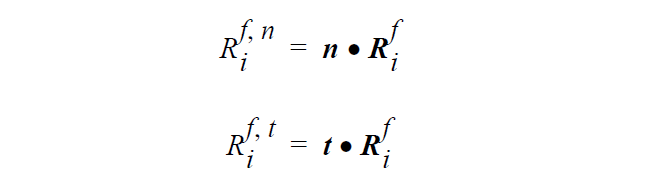
n and t are the unit normal and tangent vectors at the boundary (evaluated at the centroid along the boundary of an element) and \(R_i^f\) is the vector form of the weighted residual equation. This rotation is performed after all weak boundary conditions have been applied, but prior to application of strong boundary conditions. Thus any weak contributions to the vector equation are retained throughout the rotation. \(R_i^{fn}\) is the normal component of the vector equation and \(R_i^{ft}\) is the tangent component of the vector equation. Note that the equations are rotated after they have been integrated rather than before; thus, the new residual equations are only strictly in normal-tangential form along straight boundaries (along curved boundaries there may be some error which becomes small as the element size decreases).
In Goma, rotated boundary conditions cause rotation of the vector equation on an element side if there are no Dirichlet conditions applied to that vector equation and if the total number of independent rotated conditions is less than the number of dimensions of the physical problem (i.e., in a 2D problem, the vector equation is rotated only when one independent rotated condition exists at that node).
Thus along any rotated boundary, the three vector equations (e.g. x, y, and z mesh equations) are replaced by three new equations as specified in this section. The user can decide to replace the component equations by rotated forms of the equations (or even unrotated forms of the equations), or to replace the component equations by boundary conditions. These specifications also dictate how to calculate the tangent vectors which are sometimes ill-defined in 3D. This section is designed to accommodate an arbitrary number of rotation specifications listed in the Goma input between Rotation Specifications = and END OF ROT.
All of this behavior is implemented through the overloaded ROT input card. There are three types of ROT cards depending on whether the condition applies on a surface, an edge or a vertex. Goma makes no assumptions about the topology of the mesh surfaces; all the topology is defined through the ROT card. In this implementation, a surface is defined as a side-set, an edge is defined as the intersection of two side-sets, and a vertex is defined as the intersection of three side-sets at a single node. Although all three types of input cards start with ROT =, we list them as three independent cards to make the discussion more straightforward. As nodes that are contained on edges must also be contained on the adjacent surfaces, these rotation specifications have a hierarchy – vertex, edge, surface – such that vertex conditions override edge conditions which override surface conditions.
Note: it is possible to solve a 3D problem with rotated boundaries by only creating rotation specifications for those boundaries, and letting Goma determine the behavior at the remaining boundaries. However, this is a dangerous practice; it is much better to explicitly tell Goma how to treat all boundaries so that the behavior is well defined. An important example is the intersection of a rotated boundary and an unrotated boundary, it is still a rotated boundary and requires an edge ROT specification.