
Category 13: Potential Equation#
The Potential equation is a Laplace equation for the voltage (potential) given a charge distribution in a dielectric medium or a voltage or current boundary condition in an electrically conductive medium. The following boundary conditions allow the current or voltage to be set on a boundary.
CURRENT#
BC = CURRENT SS <bc_id> <float>
Description / Usage#
(WIC/POTENTIAL)
This card specifies the electrical current density at a given boundary.
Definitions of the input parameters are as follows:
CURRENT |
Name of the boundary condition (<bc_name>). |
SS |
Type of boundary condition (<bc_type>), where SS denotes side set in the EXODUS II database. |
<bc_id> |
The boundary flag identifier, an integer associated with <bc_type> that identifies the boundary location (side set in EXODUS II) in the problem domain. |
<float> |
Value of current density (in A/ \(m^2\) or A/ \(cm^2\), depending on units of length scale used in the problem). |
Examples#
An example input card:
BC = CURRENT SS 1 -0.05
Technical Discussion#
No Discussion.
CURRENT_USER#
BC = CURRENT_USER SS <bc_id> <float_list>
Description / Usage#
(WIC/POTENTIAL)
This boundary condition card is used to define a routine for a user-defined electrical current density model. Definitions of the input parameters are as follows:
CURRENT_USER |
Name of the boundary condition (<bc_name>). |
SS |
Type of boundary condition (<bc_type>), where SS denotes side set in the EXODUS II database. |
<bc_id> |
The boundary flag identifier, an integer associated with <bc_type> that identifies the boundary location (side set in EXODUS II) in the problem domain. |
<float_list> |
A list of float values separated by spaces which will be passed to the user-defined subroutines so the user can vary the parameters of the boundary condition. This list of float values is passed as a one-dimensional double array to the appropriate C function. |
Examples#
The following is a sample input card:
BC = CURRENT_USER SS 100 10.0 3.14159
Technical Discussion#
No Discussion.
VOLT#
BC = VOLT NS <bc_id> <float1> [float2]
Description / Usage#
(DC/POTENTIAL)
This Dirichlet boundary condition card is used to set a constant voltage. Definitions of the input parameters are as follows:
VOLT |
Name of the boundary condition (<bc_name>). |
NS |
Type of boundary condition (<bc_type>), where NS denotes node set in the EXODUS II database. |
<bc_id> |
The boundary flag identifier, an integer associated with <bc_type> that identifies the boundary location (node set in EXODUS II) in the problem domain. |
<float1> |
Value of voltage. |
[float2] |
An optional parameter (that serves as a flag to the code for a Dirichlet boundary condition). If a value is present, and is not -1.0, the condition is applied as a residual equation. Otherwise, it is a “hard set” condition and is eliminated from the matrix. The residual method must be used when this Dirichlet boundary condition is used as a parameter in automatic continuation sequences. |
Examples#
Following is a sample card:
BC = VOLT NS 3 -0.22
Technical Discussion#
No Discussion.
CURRENT_BV#
BC = CURRENT_BV SS <bc_id> <integer> <floatlist>
Description / Usage#
(WIC/POTENTIAL)
The CURRENT_BV card enables the specification of variable electrical current density as given by Butler-Volmer kinetics and the Faraday’s law at the specified boundary (namely, an electrode surface).
The <floatlist> has seven parameters for this boundary condition; definitions of the input parameters are as follows:
CURRENT_BV |
Name of the boundary condition (<bc_name>). |
SS |
Type of boundary condition (<bc_type>), where SS denotes side set in the EXODUS II database. |
<bc_id> |
The boundary flag identifier, an integer associated with <bc_type> that identifies the boundary location (side set in EXODUS II) in the problem domain. |
<integer> |
Species number of concentration. |
<float1> |
Stoichiometric coefficient. |
<float2> |
Kinetic rate constant. |
<float3> |
Reaction order. |
<float4> |
Anodic direction transfer coefficient. |
<float5> |
Cathodic direction transfer coefficient. |
<float6> |
Electrode potential or applied voltage. |
<float7> |
Theoretical open-circuit potential. |
Examples#
An example input card:
BC = CURRENT_BV SS 1 0 -1.0 0.000002 1.0 0.21 0.21 -0.65 -0.22
Technical Discussion#
Users are referred to Chen (2000) for details of the Butler-Volmer model and also Newman (1991), particularly Equations 8.6 and 8.10 and Chapter 8, pp. 188-189 in the latter.
References#
GTM-025.0: Modeling diffusion and migration transport of charged species in dilute electrolyte solutions: GOMA implementation and sample computed predictions from a case study of electroplating, K. S. Chen, September 21, 2000
Newman, “Electrochemical Systems”, Second Edition, Prentice-Hall, Inc. (1991).
CURRENT_HOR#
BC = CURRENT_HOR SS <bc_id> <integer> <floatlist>
Description / Usage#
(WIC/POTENTIAL)
The CURRENT_HOR card enables the specification of the variable current density as given by linearized Butler-Volmer kinetics (such as that for the hydrogen-oxidation reaction in polymer-electrolyte-membrane fuel cells) at the specified boundary (i.e., at the electrode surface).
The <floatlist> consists of 9 values; definitions of the input parameters are as follows:
CURRENT_HOR |
Name of the boundary condition (<bc_name>). |
SS |
Type of boundary condition (<bc_type>), where SS denotes side set in the EXODUS II database. |
<bc_id> |
The boundary flag identifier, an integer associated with <bc_type> that identifies the boundary location (side set in EXODUS II) in the problem domain. |
<integer> |
Species number of concentration. |
<float1> |
Product of interfacial area per unit volume by exchange current density, \(ai_0\), in units of A/ \(cm^3\). |
<float2> |
Catalyst layer or catalyzed electrode thickness, H, in unit of cm. |
<float3> |
Reference concentration, \(c_{ref}\), in units of moles/ \(cm^3\). |
<float4> |
Anodic direction transfer coefficient, \(\alpha_a\). |
<float5> |
Cathodic direction transfer coefficient, \(\alpha_c\). |
<float6> |
Temperature, T, in unit of K. |
<float7> |
Theoretical open-circuit potential, \(U_0\), in unit of V. |
<float8> |
Reaction order, \(\beta\). |
<float9> |
Electrode potential, V, in unit of V. |
Examples#
The following is a sample input card:
BC = CURRENT_HOR SS 14 0 1000. 0.001 4.e-5 1. 1. 353. 0. 0.5 0.
Technical Discussion#
For electrochemical reactions such as the hydrogen-oxidation reaction (HOR), surface overpotential is relatively small such that the Butler-Volmer kinetic model can be linearized to yield a simplified equation for computing current density:
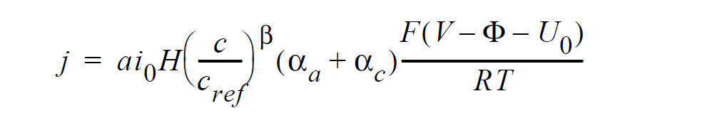
where j is current density in units of A/ \(cm^2\); \(ai_0\) denotes the product of interfacial area per unit volume by exchange current density, which has units of A/ \(cm^3\); H is the catalyst layer or catalyzed electrode thickness in unit of cm; c and \(c_{ref}\) are, respectively, species and reference molar concentrations in units of moles/ \(cm^3\); \(\beta\) is reaction order; \(\alpha_a\) and \(\alpha_c\) are, respetively, the anodic and cathodic transfer coefficients; F is the Faraday’s constant ( 96487 C/mole); R is the universal gasl constant ( 8.314 J/mole-K); T is temperature in unit of K; V and \(\phi\) are, respectively, the electrode and electrolyte potentials in unit of V; \(U_0\) and is the open-circuit potential in unit of V.
References#
Newman, Electrochemical Systems, 2nd Edition, Prentice-Hall, NJ (1991).
K. S. Chen and M. A. Hickner, “Modeling PEM fuel cell performance using the finiteelement method and a fully-coupled implicit solution scheme via Newton’s technique”, in ASME Proceedings of FUELCELL2006-97032 (2006).
CURRENT_ORR#
BC = CURRENT_ORR SS <bc_id> <integer> <floatlist>
Description / Usage#
(WIC/POTENTIAL)
The CURRENT_ORR card enables the specification of the variable current density as given by the Tafel kinetics (such as that for the oxygen-reduction reaction in polymerelectrolyte- membrane fuel cells) at the specified boundary (i.e., at the electrode surface).
The <floatlist> consists of 8 values; definitions of the input parameters are as follows:
CURRENT_ORR |
Name of the boundary condition (<bc_name>). |
SS |
Type of boundary condition (<bc_type>), where SS denotes side set in the EXODUS II database. |
<bc_id> |
The boundary flag identifier, an integer associated with <bc_type> that identifies the boundary location (side set in EXODUS II) in the problem domain. |
<integer> |
Species number of concentration. |
<float1> |
Product of interfacial area per unit volume by exchange current density, \(ai_0\), in units of A/ \(cm^3\). |
<float2> |
Catalyst layer or catalyzed electrode thickness, H, in unit of cm. |
<float3> |
Reference concentration, \(c_{ref}\), in units of moles/ \(cm^3\). |
<float4> |
Cathodic direction transfer coefficient, \(\alpha_c\). |
<float5> |
Temperature, T, in unit of K. |
<float6> |
Electrode potential, V, in unit of V. |
<float7> |
Theoretical open-circuit potential, \(U_0\), in unit of V. |
<float8> |
Reaction order, \(\beta\). |
Examples#
The following is a sample input card:
BC = CURRENT_ORR SS 15 1 0.01 0.001 4.e-5 1. 353. 0.7 1.18 1.
Technical Discussion#
For electrochemical reactions such as the oxygen-reduction reaction (ORR), surface overpotential is large and negative such that the first exponential term in the Butler- Volmer kinetic model is much smaller than the second term and thus can be dropped to yield the Tafel kinetic model for computing current density:
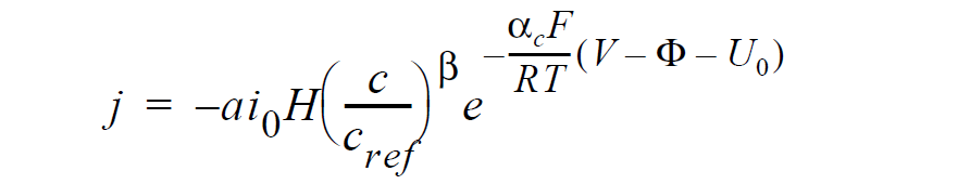
here j is current density in units of A/ \(cm^2\); \(ai_0\) denotes the product of interfacial area per unit volume by exchange current density, which has units of A/ \(cm^3\); H is the catalyst layer or catalyzed electrode thickness in unit of cm; c and \(c_{ref}\) are, respectively, species and reference molar concentrations in units of moles/ \(cm^3\); \(\beta\) is reaction order; \(\alpha_c\) is the anodic and cathodic transfer coefficient; F is the Faraday’s constant ( 96487 C/mole); R is the universal gasl constant ( 8.314 J/mole-K); T is temperature in unit of K; V and \(\phi\) are, respectively, the electrode and electrolyte potentials in unit of V; and \(U_0\) is the open-circuit potential in unit of V.
References#
Newman, Electrochemical Systems, 2nd Edition, Prentice-Hall, NJ (1991).
K. S. Chen and M. A. Hickner, “Modeling PEM fuel cell performance using the finiteelement method and a fully-coupled implicit solution scheme via Newton’s technique”, in ASME Proceedings of FUELCELL2006-97032 (2006).
VOLT_USER#
BC = VOLT_USER SS <bc_id> <float_list>
Description / Usage#
(WIC/POTENTIAL)
This boundary condition card is used to specify a voltage or potential computed via a user-defined function. Definitions of the input parameters are as follows:
VOLT_USER |
Name of the boundary condition (<bc_name>). |
SS |
Type of boundary condition (<bc_type>), where SS denotes side set in the EXODUS II database. |
<bc_id> |
The boundary flag identifier, an integer associated with <bc_type> that identifies the boundary location (side set in EXODUS II) in the problem domain. |
<float_list> |
A list of float values separated by spaces which will be passed to the user-defined subroutines so the user can vary the parameters of the boundary condition. This list of float values is passed as a one-dimensional double array to the appropriate C function. |
Examples#
The following is a sample input card:
BC = VOLT_USER SS 14 0.33 1000. 0.001 4e-5 1. 1. 353. 0.
Technical Discussion#
In the VOLT_USER model currently implemented in GOMA, the electrolyte potential is given by the linearized Butler-Volmer kinetic model as in the hydrogen-oxidation reaction of a hydrogen-fueled polymer-electrolyte-membrane fuel cell. See the user_bc.c routine for details.
References#
No References.