
Category 5: Energy Equations#
The following conditions are applied as boundary conditions to the energy equation. These conditions include strong Dirichlet conditions, such as hard sets on temperature on a boundary as a constant or function of position, weak-form conditions, such as a specified heat flux from a convective heat transfer model or a constant flux, and a host of interfacial conditions for phase change (viz. latent heat effects), etc. The energy equation is of course a scalar equation. Some with a molten metal surface. These conditions will also apply in general to the porous energy equation (see Porous Energy). highly specialized equations are also available, such as a heat flux model for a laser interaction
T#
BC = T NS <bc_id> <float1> [float2]
Description / Usage#
(DC/ENERGY)
This Dirichlet boundary condition card is used to set constant temperature. Definitions of the input parameters are as follows:
T |
Name of the boundary condition (<bc_name>). |
NS |
Type of boundary condition (<bc_type>), where NS denotes node set in the EXODUS II database. |
<bc_id> |
The boundary flag identifier, an integer associated with <bc_type> that identifies the boundary location (node set in EXODUS II) in the problem domain. |
<float1> |
Value of temperature. |
[float2] |
An optional parameter (that serves as a flag to the code for a Dirichlet boundary condition). If a value is present, and is not -1.0, the condition is applied as a residual equation. Otherwise, it is a “hard set” condition and is eliminated from the matrix. The residual method must be used when this Dirichlet boundary condition is used as a parameter in automatic continuation sequences. |
Examples#
The following is a sample input card:
BC = T NS 100 273.13
Technical Discussion#
No Discussion.
T_USER#
BC = T_USER SS <bc_id> <float_list>
Description / Usage#
(PCC/ENERGY)
This boundary condition card is used to call a routine for a user-defined temperature. Specification is made via the function tuser in file “user_bc.c.” Definitions of the input parameters are as follows:
T_USER |
Name of the boundary condition (<bc_name>). |
SS |
Type of boundary condition (<bc_type>), where SS denotes side set in the EXODUS II database. |
<bc_id> |
The boundary flag identifier, an integer associated with <bc_type> that identifies the boundary location (side set in EXODUS II) in the problem domain. |
<float_list> |
A list of float values separated by spaces which will be passed to the user-defined subroutine so the user can vary the parameters of the boundary condition. This list of float values is passed as a one-dimensional double array to the appropriate C function in file user_bc.c. |
Examples#
The following is a sample input card with two parameters passed to function tuser:
BC = T_USER SS 100 273.13 100.0
Technical Discussion#
No Discussion.
References#
No References.
QCONV#
BC = QCONV SS <bc_id> <float1> <float2>
Description / Usage#
(WIC/ENERGY)
This boundary condition card specifies convective heat flux. Definitions of the input parameters are as follows:
QCONV |
Name of the boundary condition (<bc_name>). |
SS |
Type of boundary condition (<bc_type>), where SS denotes side set in the EXODUS II database. |
<bc_id> |
The boundary flag identifier, an integer associated with <bc_type> that identifies the boundary location (side set in EXODUS II) in the problem domain. |
<float1> |
h, heat transfer coefficient. |
<float2> |
\(T_s\), sink temperature. |
Examples#
The following is a sample card:
BC = QCONV SS 100 10.0 293.0
Technical Discussion#
The convective heat flux is defined as
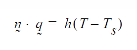
where h and \(T_s\) are the convective heat transfer coefficient and the sink temperature, respectively.
QRAD#
BC = QRAD SS <bc_id> <float_list>
Description / Usage#
(WIC/ENERGY)
This boundary condition card specifies heat flux using both convective and radiative terms. The <float_list> has four parameters; definitions of the input parameters are as follows:
QRAD |
Name of the boundary condition (<bc_name>). |
SS |
Type of boundary condition (<bc_type>), where SS denotes side set in the EXODUS II database. |
<bc_id> |
The boundary flag identifier, an integer associated with <bc_type> that identifies the boundary location (side set in EXODUS II) in the problem domain. |
<float1> |
h, convective heat transfer coefficient. |
<float2> |
\(T_s\), sink temperature. |
<float3> |
\(\varepsilon\), total hemispherical emissivity. |
<float4> |
\(\sigma\), Stefan-Boltzmann constant. |
Examples#
The following is a sample card:
BC = QRAD SS 100 10.0 273.0 0.3 5.6697e-8
Technical Discussion#
The heat flux definition for this card is a combined convective and radiative formulation:
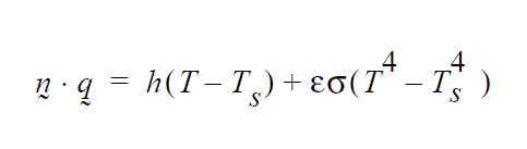
where h and \(T_s\) are the convective heat transfer coefficient and the sink temperature, and \(\varepsilon\) and \(\sigma\) are the total hemispherical emissivity and Stefan-Boltzmann constant, respectively. The latter constant has been made an input parameter rather than a code constant so that the user can specify its value in units that are consistent for the problem being modeled.
The QRAD boundary condition can be used in place of QCONV by simply setting the emissivity value to zero.
QSIDE#
BC = QSIDE SS <bc_id> <float1>
Description / Usage#
(WIC/ENERGY)
This boundary condition card is used to specify a constant heat flux. Definitions of the input parameters are as follows:
QSIDE |
Name of the boundary condition (<bc_name>). |
SS |
Type of boundary condition (<bc_type>), where SS denotes side set in the EXODUS II database. |
<bc_id> |
The boundary flag identifier, an integer associated with <bc_type> that identifies the boundary location (side set in EXODUS II) in the problem domain. |
<float1> |
Value of heat flux. A positive value implies that energy is being added to system; a negative value implies energy is being taken from the system through the boundary. |
Examples#
The following is a sample card:
BC = QSIDE SS 22 1.50
Technical Discussion#
The mathematical form of the boundary condition.

T_CONTACT_RESIS, T_CONTACT_RESIS_2#
BC = T_CONTACT_RESIS SS <bc_id> <int1> <int2> <float1>
BC = T_CONTACT_RESIS_2 SS <bc_id> <int2> <int1> <float1>
Description / Usage#
(WIC/ENERGY)
This boundary condition set is used to specify a thermal contact resistance at an interface between two mesh regions defined by a side set. Please see special usage notes below regarding proper side-set specification and the reasons that both BC cards are required for an internal interface. NOTE that the temperature field MUST be interpolated with the discontinous versions of Q1 or Q2, viz. Q1_D and Q2_D. Definitions of the input parameters are as follows:
T_CONTACT_RESIS |
Name of the boundary condition (<bc_name>). |
SS |
Type of boundary condition (<bc_type>), where SS denotes side set in the EXODUS II database. Note this side set MUST contain elements on both sides of the interface. |
<bc_id> |
The boundary flag identifier, an integer associated with <bc_type> that identifies the boundary location (side set in EXODUS II) in the problem domain. |
<int1> |
Material/region ID associated with first material. |
<int2> |
Material/region ID associated with second material. Note that these material IDs are reversed on the second BC. |
<float1> |
Value contact resistance in units of thermal conductivity divided by length. |
Examples#
The following is a sample card:
BC = T_CONTACT_RESIS SS 3 1 2 10.0
BC = T_CONTACT_RESIS_2 SS 3 2 1 10.0
Note that both boundary condition cards are required at an internal interface. In this case the interface divides mesh/material ID 1 and 2. Note also how these material IDs are reversed on the second card. These conditions apply a thermal contact resistance of 10. (units of thermal conductivity divided by length) at the interface defined by SS 3.
Technical Discussion#
The mathematical form of the boundary condition.
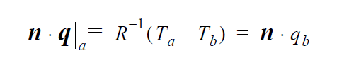
The flux into the interface from material “a” is equivalent to that into material “b”, both equal to the temperature jump across the interface times the contact resistance \(R^{-1}\).
The side set to which this boundary condition is applied must contain elements on both sides of the interface. Look up any special commands in your mesh generator to make sure this occurs. In CUBIT, for example, you have to add “wrt volume 1 2” like qualifiers on the side set command. The reason for the “double application” of this condition is to pick up the all the terms from both sides of the interface with the proper sign. The nodes at the interface have two temperatures, one from each side, and so two weak form applications of this equation are required, one from each side.
QNOBC#
BC = QNOBC SS <bc_id>
Description / Usage#
(WIC/ENERGY)
This boundary condition card applies the open boundary condition equivalent on the energy equation (see momentum open BC FLOW_STRESSNOBC)
QNOBC |
Name of the boundary condition. |
SS |
Type of boundary condition (<bc_type>), where SS denotes side set in the EXODUS II database. |
<bc_id> |
The boundary flag identifier, an integer associated with <bc_type> that identifies the boundary location (side set in EXODUS II) in the problem domain. |
Examples#
Following is a sample card:
BC = QNOBC SS 3
Here the BC is applied to SS 3
Technical Discussion#
The finite element formulation of the energy equation generates boundary integrals of the form:
where \(\mathbf{q}\) is the heat flux.
This boundary condition adds this term back in at the boundary avoiding the natural boundary condition.
References#
Griffiths, D.F., “The ‘no boundary condition’ outflow boundary condition,” IJNMF, 24, 393-411, (1997)
Sani, R.L., and P.M. Gresho, “Resume and remarks on the open boundary condition minisymposium,” IJNMF, 18, 983-1008, (1994).
QUSER#
BC = QUSER SS <bc_id> <float_list>
Description / Usage#
(WIC/ENERGY)
This boundary condition card is used to call a routine for a user-defined heat flux model. Definitions of the input parameters are as follows:
QUSER |
Name of the boundary condition (<bc_name>). |
SS |
Type of boundary condition (<bc_type>), where SS denotes side set in the EXODUS II database. |
<bc_id> |
The boundary flag identifier, an integer associated with <bc_type> that identifies the boundary location (side set in EXODUS II) in the problem domain. |
<float_list> |
A list of float values separated by spaces which will be passed to the user-defined subroutines so the user can vary the parameters of the boundary condition. This list of float values is passed as a one-dimensional double array to the quser_surf C function in file user_bc.c. |
Examples#
The following is a sample input card for a heat flux model requiring two parameters:
BC = QUSER SS 100 10.0 3.14159
Technical Discussion#
No Discussion.
Q_VELO_SLIP#
BC = Q_VELO_SLIP SS <bc_id>
Description / Usage#
(WIC/ENERGY)
This boundary condition card is used to calculate the surface integral for viscous heating due to slip in the tangential velocity component on a surface. Definitions of the input parameters are as follows:
Q_VELO_SLIP |
Name of the boundary condition (<bc_name>). |
SS |
Type of boundary condition (<bc_type>), where SS denotes side set in the EXODUS II database. |
<bc_id> |
The boundary flag identifier, an integer associated with <bc_type> that identifies the boundary location (side set in EXODUS II) in the problem domain. |
Examples#
The following is a sample input card:
BC = Q_VELO_SLIP_BC SS 10
Technical Discussion#
Use of this boundary condition requires specification of the slip velocity components by using either the VELO_SLIP or VELO_SLIP_ROT boundary condition.
Q_LASER_WELD#
BC = Q_LASER_WELD SS <bc_id> <float_list>
Description / Usage#
(WIC/ENERGY)
This boundary condition card specifies the thermal boundary conditions for laser welding. The <float_list> requires twenty-seven values be specified; definitions of the input parameters are as follows:
Q_LASER_WELD |
Name of the boundary condition (<bc_name>). |
SS |
Type of boundary condition (<bc_type>), where SS denotes side set in the EXODUS II database. |
<bc_id> |
The boundary flag identifier, an integer associated with <bc_type> that identifies the boundary location (side set in EXODUS II) in the problem domain. |
<float1> |
Nominal power of laser. |
<float2> |
Power of laser at base state (simmer). |
<float3> |
Base value of surface absorptivity. |
<float4> |
Switch to allow tracking of normal component of liquid surface relative to laser beam axis for surface absorption (0 = OFF, 1 = ON) |
<float5> |
Cutoff time for laser power. |
<float6> |
Time at which laser power drops to 1/e. |
<float7> |
For pulse weld, the laser power overshoot (%) of peak power at time to reach peak laser power. |
<float8> |
Radius of laser beam. |
<float9> |
For pulse weld, the time for laser pulse to reach peak power. |
<float10> |
For pulse weld, the time for laser pulse to reach steady state in power. |
<float11> |
Switch to either activate laser power distribution from beam center based on absolute distance (0) or based on radial distance in 2D plane (1). |
<float12> |
Location of laser beam center (x-coordinate). |
<float13> |
Location of laser beam center (y-coordinate). |
<float14> |
Location of laser beam center (z-coordinate). |
<float15> |
Laser beam orientation, normal to x-coordinate of body. |
<float16> |
Laser beam orientation, normal to y-coordinate of body. |
<float17> |
Laser beam orientation, normal to z-coordinate of body. |
<float18> |
For pulse weld, spot frequency. |
<float19> |
For pulse weld, total number of spots to simulate. |
<float20> |
Switch to set type of weld simulation. (0=pulse weld, 1=linear continuous weld, -1=pseudo pulse weld, 2=sinusoidal continous weld) |
<float21> |
For pulse weld, spacing of spots. |
<float22> |
For radial traverse continuous weld, radius of beam travel. |
<float23> |
Switch to activate beam shadowing for lap weld (0=OFF, 1=ON). Currently only active for ALE simulations. |
<float24> |
Not active, should be set to zero. |
<float25> |
For continuous weld, laser beam travel speed in xdirection (u velocity). |
<float26> |
For continuous weld, laser beam travel speed in ydirection (v velocity). |
<float27> |
For continuous weld, laser beam travel speed in zdirection (w velocity). |
Examples#
The following is a sample input card:
BC = Q_LASER_WELD SS 10 4.774648293 0 0.4 1 1 1.01 4.774648293 0.2
0.01 0.01 1 0.005 0 -0.198 -1 0 0 0.025 1 1 0.2032 -1000 0 0 0 0 0.0254
Technical Discussion#
Several required pieces of information to use this boundary condition are not in final form, and the user can expect future changes and improvements. Below is a listing of some of these parameters:
This boundary condition requires that node sets 1001 is defined in the EXODUS II file. NS 1001 should include the point at the center of the keyhole on the surface closest to the beam.
Currently the laser flux distribution is set as a fixed exponential distribution. Plans are to include more options including a user-defined exponential and a TABLE option.
Correlations are used to specify the evaporation energy loss. Currently only iron and ice correlations exist; the appropriate correlation is selected based on the value set for the Solidus Temperature (in Thermal Properties portion of the material file).
Q_VAPOR_BC#
BC = Q_VAPOR SS <bc_id> <float_list>
Description / Usage#
(WIC/ENERGY)
This boundary condition card is used to specify heat loss due to evaporation. It is typically used in conjunction with Q_LASER_WELD.
Q_VAPOR |
Name of the boundary condition (<bc_name>). |
SS |
Type of boundary condition (<bc_type>), where SS denotes side set in the EXODUS II database. |
<bc_id> |
The boundary flag identifier, an integer associated with <bc_type> that identifies the boundary location (side set in EXODUS II) in the problem domain. |
<float1> |
Temperature scale. |
<float2> |
Energy unit scale. |
Examples#
The following is a sample input card:
BC = Q_VAPOR SS 10 100. 10.
Technical Discussion#
This condition is turned on above the boiling point, which is story in the melting point solidus temperature.
VP_EQUIL#
BC = VP_EQUIL SS <bc_id> <integer_list> <float>
Description / Usage#
(SIC/ENERGY)
This boundary condition card is used to equate solvent partial pressure in the gas between the porous medium and the external phase. The condition is similar to the solid-liquid interface conditions that apply to interfaces between a porous medium and an external gas phase (in which the energy equation is used to solve for solvent concentration in the gas phase). This boundary condition is still under development.
There are three values to be specified for the <integer_list>; definitions of the input parameters are as follows:
VP_EQUIL |
Name of the boundary condition (<bc_name>). |
SS |
Type of boundary condition (<bc_type>), where SS denotes side set in the EXODUS II database. |
<bc_id> |
The boundary flag identifier, an integer associated with <bc_type> that identifies the boundary location (side set in EXODUS II) in the problem domain. |
<integer1> |
Element block ID of solid, porous phase from the EXODUS II database. |
<integer2> |
Element block ID of gas phase from the EXODUS II database. |
<integer3> |
Species number of liquid phase in porous medium. |
<float> |
Ambient pressure in external gas phase. |
Examples#
The following is a sample input card:
BC = VP_EQUIL SS 100 1 2 0 0.0
where the solid/porous phase is present in element block 1 and the gas phase is present in element block 2. The external gas phase pressure has been set to 0.0.
Technical Discussion#
No Discussion.
LATENT_HEAT#
BC = LATENT_HEAT SS <bc_id> <integer> <float_list>
Description / Usage#
(WIC/ENERGY)
This boundary condition card is used for latent heat release/adsorption at an external interface. The flux quantity is specified on a per mass basis so the heat and mass transfer coefficients are in units of L/t.
The <float_list> has three values to be specified; definitions of the input parameters are as follows:
LATENT_HEAT |
Name of the boundary condition (<bc_name>). |
SS |
Type of boundary condition (<bc_type>), where SS denotes side set in the EXODUS II database. |
<bc_id> |
The boundary flag identifier, an integer associated with <bc_type> that identifies the boundary location (side set in EXODUS II) in the problem domain. |
<integer> |
Species number. |
<float1> |
Latent Heat for the pure w+1 species component. |
<float2> |
Mass transfer coefficient for the w+1 species component. |
<float3> |
Sink concentration for the w+1 species component. |
The float values on this card apply to the bulk species (i.e., the w+1 component) in a multi-species problem and in the case of a pure fluid. Important usage comments are contained in the Technical Discussion below.
Examples#
The following is a sample input card:
BC = LATENT_HEAT SS 3 0 540. 0.1 0.
Two more detailed examples are contained in the Technical Discussion section.
Technical Discussion#
The LATENT_HEAT boundary condition has the form
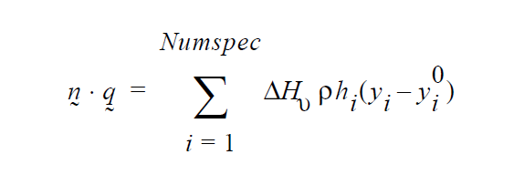
where \(\underline{n}\) is the outward normal to the surface, \(\underline{q}\) is the heat flux vector, \(\Delta\) \(H_\nu\) is the heat of vaporization, \(\rho\) is density, \(h_i\) is the heat-transfer coefficient for species i, and \(y^0_i\) is the reference concentration of species i at locations remote from the boundary; the summation is over the number of species in the material block. The manner of usage of this boundary condition depends on the set of conditions characterizing the problem; example conditions are described below.
This card is used for external surfaces for which heat transfer and mass transfer beyond it’s surfaces are governed by heat and mass transfer coefficients. The LATENT_HEAT BC is applied to the energy equation so a heat flux can be specified for thermal problems alone. The mass transfer portion of the vaporization phenomenon is handled by the KIN_LEAK and YFLUX BC cards; these boundary conditions are applied to the mesh equations. The LATENT_HEAT_INTERNAL card should be used for internal surfaces, or interfaces, at which transfer is governed by actual physics being modeled as a part of the problem.
When vaporization of a pure liquid is being modeled, there is only a ’single species’, the bulk volatile liquid. In the single species case, the Species Properties of the corresponding material file (which includes the Heat of Vaporization card) is not even read so the actual value of the latent heat of vaporization must be entered on the*LATENT_HEAT* card (<float1>). If multiple species are present, the latent heat value for each species is entered in the material file and the LATENT_HEAT card does for the energy equation the same thing the KIN_LEAK card does for the mesh equation (i.e., collects the flux conditions that apply for each species).
For mass transfer in the single species/pure liquid case, the mass transfer coefficient is specified on the KIN_LEAK card. When multiple species are present, the mass transfer coefficient and driving concentration on the KIN_LEAK card are set to zero and the appropriate coefficient and driving concentration are set for each species on the YFLUX card, one for each species. The KIN_LEAK card (or the LATENT HEAT for energy flux) must be present to signal Goma to look for multiple YFLUX cards.
The latent heat quantity is specified on a per mass basis and the transfer coefficients are in units of L/t. Some examples of LATENT_HEAT application follow:
Pure Liquid Case
BC = LATENT HEAT SS 3 0 540. 0.1 0.
BC = KIN_LEAK SS 3 0.1 0.
Two-Species Case
BC = LATENT HEAT SS 3 0 0. 0.1 0.
BC = KIN_LEAK SS 3 0. 0.
BC = YFLUX SS 3 0 0.12 0.
BC = YFLUX SS 3 1 0.05 0.
plus, in the corresponding material file:
---Species Properties
Diffusion Constitutive Equation= FICKIAN
Diffusivity = CONSTANT   0   1.e-8
Latent Heat Vaporization = CONSTANT   0   540.
Latent Heat Fusion = CONSTANT   0   0.
Vapor Pressure = CONSTANT   0   0.
Species Volume Expansion = CONSTANT   0   1.
Reference Concentration = CONSTANT   0   0.
Diffusivity = CONSTANT   1   1.e-6
Latent Heat Vaporization = CONSTANT   1   125.
Latent Heat Fusion = CONSTANT   1   0.
Vapor Pressure = CONSTANT   1   0.
Species Volume Expansion = CONSTANT   1   1.
Reference Concentration = CONSTANT   1   0.
References#
No References.
LATENT_HEAT_INTERNAL#
BC = LATENT_HEAT_INTERNAL SS {char_string} <integer_list> <float>
Description / Usage#
(WIC/ENERGY)
This boundary condition card is used for latent heat release/adsorption at an internal interface. See usage comments in the Technical Discussion.
The <integer_list> requires two values be specified; definitions of the input parameters are as follows:
LATENT_HEAT_INTERNAL |
Name of the boundary condition (<bc_name>). |
SS |
Type of boundary condition (<bc_type>), where SS denotes side set in the EXODUS II database. |
<bc_id> |
The boundary flag identifier, an integer associated with <bc_type> that identifies the boundary location (side set in EXODUS II) in the problem domain. |
{char_string} |
Variable name with the following permissible values:
|
<integer1> |
NOT ACTIVE. Any integer will do. |
<integer2> |
NOT ACTIVE. Any integer will do. |
<float3> |
Value of latent heat of vaporization/fusion for a pure material case, in units of Energy/mass. |
Examples#
The following is a sample input card:
BC = LATENT_HEAT_INTERNAL SS 40 SOLID_LIQUID 1 2 2.6e5
Technical Discussion#
The LATENT_HEAT_INTERNAL card should be used for internal surfaces, or interfaces, at which transfer is governed by actual physics being modeled as a part of the problem. See LATENT_HEAT card for further information.