
Density#
Density = {model_name} {float_list} [M/L3]
Description / Usage#
This required card is used to specify the model, and all associated parameters, for density. Definitions of the input parameters are as follows:
- {model_name}
Name of the density model. This parameter can have one of the following values: CONSTANT, USER, FILL, SUSPENSION, IDEAL_GAS, THERMAL_BATTERY, LEVEL_SET, CONST_PHASE_FUNCTION, FOAM, REACTIVE_FOAM, or SOLVENT_POLYMER. Boussinesq models can be selected through the Navier-Stokes Source card.
- {float_list}
One or more floating point numbers (<float1> through <floatn> whose interpretation is determined by the selection for {model_name}.
Thus, choices for {model_name} and the accompanying parameter list are given below; additional guidance to the user can be found in the Technical Discussion section following the Examples.
- CONSTANT <float1>
For the CONSTANT density model, {float_list} is a single value:
<float1> - Density [M/L3 ]
- USER <float1> … <floatn>
For a user-defined model, the set of parameters specified as <float1> through <floatn> are defined in the function usr_density.
- FILL <float1> <float2>
The model is used with the fill equation when the location of the free surface between two fluids is tracked with a volume-of-fluid method. The {float_list} contains two values for this model, where:
<float1> - Density of the fluid in phase 1, denoted by F=1
<float2> - Density of the fluid in phase 2, denoted by F=0
This card is required when using the FILL momentum source (Navier-Stokes Source in Source Terms section of manual) since it makes of this model to compute the value of the density.
- SUSPENSION <float1> <float2> <float3>
The option is used to model a suspension where the solid particle phase and the carrier fluid have different densities. The {float_list} contains three values for this model, where:
<float1> - Species number associated with the solid particulate phase (the parser reads this as a float but it is cast as an integer when assigned).
<float2> - Density of the fluid in the carrier fluid, \(\rho_f\) .
<float3> - Density of the solid particulate phase, \(rho_s\) .
- THERMAL_BATTERY <float1> <float2>
This model is used to relate electrolyte density to field variables such as mole fraction. A simple empirical form is used, with two constants in the {float_list}:
<float1> - Base Electrolyte Density, \(p_0\).
<float2> - Constant, \(\alpha\) .
(See Technical Discussion.)
- SOLVENT_POLYMER <float1>
This density model is used primarily in problems involving drying of polymeric solutions. The single float parameter on card is specific volume of the solvent material. Note that the numerical value for this parameter must be chosen to be consistent with the specific volumes for species in the solution set with the Volumes card in the material file (discussed below).
- LEVEL_SET <float1> <float2> <float3>
This model is used to vary the density in flow regime when following an interface between two fluids using level set interface tracking. This choice assures a smooth transition in density across the zero level set contour. The {float_list} contains three values for this model, where:
<float1> - Fluid density in the negative regions of the level set function, \(\rho_–\)
<float2> - Fluid density in the positive regions of the level set function, \(\rho_+\)
<float3> - Length scale over which the transition occurs, \(\alpha\) . If this parameter is set to zero, it will default to one-half the Level Set Length Scale value already specified.
This card is required when using the LEVEL_SET momentum source model (Navier-Stokes Source in Source Terms of manual) since it makes use of this model to compute the value of the density.
- CONST_PHASE_FUNCTION <floatlist> <float1> <float2>
This model is used to vary the density in flow regime when using phase function tracking of muliple phases. This choice assures a smooth transition in density the phase boundaries. The {float_list} contains a variable number of values that depend on the number phase functions being tracked, where:
<floatlist> list of float variables equal to the number of phase functions. These are the constant densities of each phase in order from 1 to number of phase functions that are represented by each phase function.
<float1> Length scale over which the transition between one phases density to the other occurs, \(\alpha\) . If parameter is set to zero, it will default to one-half the Level Set Length Scale value already specified.
<float3> The “null” value for density. This is the value for density which will be assigned to those regions of the flow where all the phase functions are less than or equal to zero.
This card is required when using the PHASE_FUNCTION momentum source model (Navier-Stokes Source in Source Terms of manual) since it makes use of this model to compute the value of the density.
- REACTIVE_FOAM <float1>
This model is used when a constant density assumption does not apply in the model of interest, as with reactive mixtures. While this model was implemented for foam applications, the form of the density equation is quite universal. One important assumption in this model is that the volume change upon mixing is zero. The single float input is the specific volume of the N+ species (not modeled in the problem).
This model choice requires the use of the FOAM species source model - Goma will fail it is not specified. Please see the Species Source section for instructions on the FOAM model.
- CURE_SHRINKAGE <float1> <float2> <float3> <float4> <float5>
This model is used to model the density of a material that is undergoing cure shrinkage. The {float_list} contains three values for this model, where:
<float1> - Initial density of the material before cure shrinkage, \(\rho_l\)
<float2> - Final density of the material after cure shrinkage, \(\rho_f\)
<float3> - \(\alpha_m\)
<float4> - \(\alpha_g\)
<float5> - minimum value of species to enable cure shrinkage, \(Y_{min}\)
The density is computed as follows:
If the species value is greater than or equal to the minimum value, then
\[\rho = \rho_l + ((\rho_f - \rho_l) / (\alpha_m - \alpha_g)) (Y - \alpha_g)\]else
\[\rho = \rho_l + ((\rho_f - \rho_l) / (\alpha_m - \alpha_g)) (Y_{min} - \alpha_g)\]
Examples#
Following are some sample input cards:
Density = CONSTANT 1000.
Density = LEVEL_SET 0.05 0.0001 0.25
DENSITY = CONST_PHASE_FUNCTION 0.9 0.001 12.0 0.0 0.00001
Technical Discussion#
The CONSTANT density model prescribes an unchanging value for an incompressible fluid; only a single value need be specified by the user.
The USER model provides a means for the user to create a custom density model for his/her problem. This user-defined model must be incorporated by modifying the usr_density function in the file user_mp.c. The parameters needed by this model are entered in the {float_list} and are passed to the usr_density routine as an array.
The FILL model is used when the location of the interface between two fluids is tracked with an explicit volume-of-fluid method. The value of density is defined from the following:

where \(\rho_1\) and \(\rho_0\) are the phase densities obtained from the FILL density card, F is the value of the fill color function. As can be seen, \(\rho_1\) is the density value when F = 1 while \(\rho_0\) is the density value when F = 0. In the transition zone between these to extremes of F, the density will simply be a weighted average of the two values.
The SUSPENSION model is used to model a suspension where the solid particle phase and the carrier fluid have different densities. The concentration of the continuum mixture is defined by the following relationship:

where \(\phi\) is the volume fraction of the solid particulate phase, \(\rho_f\) , is the density of the fluid in the carrier fluid and \(\rho_s\), is the density of the solid particulate phase. The solid particulate phase has an associated species number as this is designates the species equation being solved for this component.
The THERMAL_BATTERY model is used to relate electrolyte density to field variables such as mole fraction. A simple empirical form is used with the density of the system being specified by the following equation,:

where \(x_i\) is the mole fraction of ionic species i, \(\rho_0\) is the base electrolyte density and is a constant.
The LEVEL_SET density model is used to vary the density in the flow regime from one phase to the other when the interface between two fluids is being followed by level set interface tracking. The model assures a smooth transition in density across the zero level set contour. The density as a function of the level set function value, \(\phi\), is as follows:
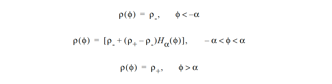
where

is a smooth Heaviside function, \(\phi\) is the value of the level set function, \(\rho_+\) and \(\rho_-\) are density values of the fluids assigned positive or negative values of the level set function, respectively, and α is the density transition length scale, that is, half the width of the transition zone between density values. Note that this value may differ from the level set length scale parameter set elsewhere.
The CONST_PHASE_FUNCTION model computes the density at a given point with the following relation:

where \(\rho_i\) are the individual phase function ( \(\phi_i\) ) densities, \(H_a( \phi_i )\) , is the smoothed Heaviside function using the length scale specified on the card. The parameter \(\rho_theta\) is the null density and will only come into play at points were all phase function values are less than zero. In theory, this shouldn’t happen for well posed problems, but in practice it is not uncommon.
The SPECIES_SOURCE and REACTIVE_FOAM models both employ the following density formula:

where \(w_j\) is the mass fraction of component j and \(V_j\) is the specific volume of species j; these two parameters are set by the Specific Volume cards in the material file. The variable N is the total number of bulk species. The variable \(V_n+1\) is the specific volume specified in the density card.