
Category 14: Fluid-Solid Interaction#
This is a special group of boundary conditions for problems in which there are two distinct material phases (fluid and solid) with relative motion between them. These BC’s provide a means to apply conditions to a moving boundary with sensitivities to variables in both phases. These problems are formulated in Goma as overset-grid or phase function problems.
LAGRANGE_NO_SLIP#
BC = LAGRANGE_NO_SLIP SS <bc_id> <integer1> <integer2>
Description / Usage#
(CONTACT_SURF/R_LAGR_MULT1)
This boundary condition is used to apply a kinematic Lagrange multiplier constraint to a solid/fluid boundary while using Goma’s overset grid capability. The condition is used when the complete fluid-structure interaction problem is being solved, viz. stresses between fluid and solid are both accommodated as is the dynamics of the structure and fluid. In contrast, Goma allows for a structure to be moved through a fluid under prescribed kinematics, and in that case a different Lagrange multiplier constraint is advocated (see LS_NO_SLIP, for example). Two integer inputs together with a sideset ID integer are required for this boundary condition:
LAGRANGE_NO_SLIP |
Name of the boundary condition. |
SS |
Type of boundary condition (<bc_type>), where NS denotes node set in the EXODUS II database. |
<bc_id> |
The boundary flag identifier, an integer associated with <bc_type> that identifies the boundary location (node set in EXODUS II) in the problem domain. |
<integer1> |
Element block ID of solid phase from the EXODUS II database. |
<integer2> |
Element block ID of liquid phase from the EXODUS II database. |
Examples#
Following is a sample card:
BC = LAGRANGE_NO_SLIP SS 2 1 2
In this case the kinematic condition (viz. a velocity match of fluid and solid at the interface) is applied to the interface imprinted by sideset 2. That side set is imprinted on the background fluid mesh. The solid material block ID is 1 in this case and the background fluid material ID is 2.
Technical Discussion#
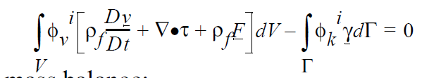
In this work, the governing equations consist of a fluid momentum balance:
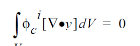
a mass balance:
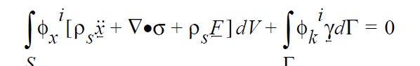
and a solid momentum balance:
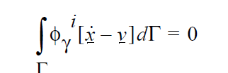
The kinematic constraint at the fluid-solid interface is:
and the level set function is evaluated at each fluid mesh node by:
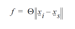
The first four equations are written in a Galerkin/Finite form, with \(\phi_i\) representing the weighting functions at node i. The first three equations are enforced at all nodes i that contain the appropriate degrees of freedom (viz. solid or fluid dofs). The fourth equation applies at the solid-liquid interface. \(\rho_f\) and \(\rho_s\) are the fluid and solid material densities, respectively, \(\underline{v}\) is the fluid velocity, \(\underline{F}\) represents any body forces such as gravity, \(\tau\) is the fluid stress tensor, \(\underline{\gamma}\) is the Lagrange multiplier vector unknown, \(\underline{\chi}\) is the solid displacement vector unknown, \(\sigma\) is the solid stress tensor, f is the level set unknown, \(\Theta\) is a step function which is -1 for points within the region occupied by the solid and +1 outside this region, \(\underline{x_i}\) and \(\underline{x_s}\) are the position vectors of a fluid node and of the closest point to it on the solid boundary, respectively, V is the fluid volume domain, S is the solid volume domain, and \(\Gamma\) is the solid boundary (interface) surface domain.
Noteworthy is that this boundary condition applies the second-to-last “kinematic” constraint.
References#
GT-026.3: Goma’s Overset Mesh Capability. Randy Schunk.
OVERSET_FLUID_SOLID/BAAIJENS_FLUID_SOLID#
BC = BAAIJENS_FLUID_SOLID PF <pf_id> <integer1> <integer2>
Description / Usage#
(EMBEDDED_SURF/R_MOMENTUM1)
This boundary condition is used to apply a traction to the fluid that comes from a solid while using Goma’s overset grid capability. The condition is used when the complete fluid-structure interaction problem is being solved, viz. stresses between fluid and solid are both accommodated as is the dynamics of the structure and fluid. The condition is applied to the fluid phase along a zero-level-set contour, hence the PF BC ID type. In another mode of usage, Goma allows for a structure to be moved through a fluid under prescribed kinematics, and in that case this condition is still applied as a solid traction to the fluid. The value of that traction is dictated by the Lagrange multiplier kinematic constraint (cf. LANGRANGE_NO_SLIP BC and LS_NO_SLIP BC). Note that the condition is applied to a boundary in the fluid defined by a phase-field function (see phase1 equation type). . Two integer inputs together with a sideset ID integer are required for this boundary condition:
BAAIJENS_FLUID_SOLD |
Name of the boundary condition. |
PF |
Type of boundary condition (<bc_type>), where PF denotes a surface defined by a phase function (level-set). |
<pf_id> |
The boundary flag identifier basically sets the number of the phase field function to which this condition applies. For now you must set this to 1, as this phase-field is hardwired to handle the imprinted fluid solid boundary. |
<integer1> |
Element block ID of solid phase from the EXODUS II database. |
<integer2> |
Element block ID of liquid phase from the EXODUS II database. |
The peculiar name was derived from a paper by Frank Baaijens, from which Goma’s formulation was generated. We are in the process of changing that name to OVERSET_FLUID_SOLID.
Examples#
Following is a sample card:
BC = BAAIJENS_FLUID_SOLID PF 1 1 2
BC = LS_NO_SLIP PF 1 1 2
This condition set applies a fluid traction condition to a surface defined by phase field 1, which is slaved to a side set that is set in the phase function slave surface capability. (see Phase Function Initialization Method).
Technical Discussion#
See discussion on LANGRANGE_NO_SLIP. This condition applies the fluid traction boundary term on the fluid momentum equation.
References#
GT-026.3
OVERSET_SOLID_FLUID/BAAIJENS_SOLID_FLUID#
BC = OVERSET_SOLID_FLUID SS <bc_id> <float_list>
Description / Usage#
(CONTACT_SURF/ MESH)
This boundary condition is used to apply a traction to a solid that comes from the fluid while using Goma’s overset grid capability. The condition is used when the complete fluid-structure interaction problem is being solved, viz. stresses between fluid and solid are both accommodated as is the dynamics of the structure and fluid. The condition is applied to the solid phase along a side set that defines the fluid/solid interface. Two integer inputs together with a sideset ID integer are required for this boundary condition:
BAAIJENS_SOLID_FLUID |
Name of the boundary condition. |
SS |
Type of boundary condition (<bc_type>), where SS denotes side set in the EXODUS II database. |
<ss_id> |
The boundary flag identifier that sets the side set number. |
<integer1> |
Element block ID of solid phase from the EXODUS II database. |
<integer2> |
Element block ID of liquid phase from the EXODUS II database. |
The peculiar name was derived from a paper by Frank Baaijens, from which Goma’s formulation was generated. We are in the process of changing that name to OVERSET_SOLID_FLUID.
Examples#
Following is a sample card set:
BC = BAAIJENS_SOLID_FLUID SS 1 2 1
BC = BAAIJENS_FLUID_SOLID PF 1 2 1
BC = LAGRANGE_NO_SLIP SS 1 2 1
Here, the BAAIJENS_SOLID_FLUID cared applies a boundary fluid traction to a solid phase defined by side set 1. In this case the solid phase material ID is 2 and the fluid phase 1.
Technical Discussion#
See discussion on LAGRANGE_NO_SLIP. Basically, this condition results in a boundary traction set by the Lagrange multiplier constraint to be applied to the solid momentum equation (note the weak term that appears on that equation).
References#
GT-026.3
F1 F2 F3 F4 F5#
BC = {F1 | F2 | F3 | F4 | F5} NS <bc_id> <float1> [float2]
Description / Usage#
(DC/R_PHASE)
This boundary condition format is used to set a constant phase function field values at node sets. Please see “phase#” equation types for a description of the variables. Each such specification (for each field being used) is made on a separate input card. These boundary conditions must be applied to node sets. Definitions of the input parameters are as follows:
{F1 | F2 | F3 | F4 | F5 } |
Two-character boundary condition name (<bc_name>) that defines which phase field variable is being set. There are a maximum of five addtional level-set/phase fields. |
NS |
Type of boundary condition (<bc_type>), where NS denotes node set in the EXODUS II database. |
<bc_id> |
The boundary flag identifier, an integer associated with <bc_type> that identifies the boundary location (node set in EXODUS II) in the problem domain. |
<float1> |
Value at which the phase field unknown will be fixed on this node set. |
[float2] |
An optional parameter (that serves as a flag to the code for a Dirichlet boundary condition). If a value is present, and is not -1.0, the condition is applied as a residual equation. Otherwise, it is a “hard set” condition and is eliminated from the matrix. The residual method must be used when this Dirichlet boundary condition is used as a parameter in automatic continuation sequences. |
Examples#
Following is a sample card which applies an phase field boundary condition to the nodes in node set 100, specifically an phase field-3 value of 1.0.
BC = F3 NS 100 1.0
Technical Discussion#
This boundary condition finds most of its use in the Phase Function interface tracking algorithm where it is used to fix the value of the color function at an inlet or outlet boundary. The phase function fields were put in to supplement Goma’s base level set capability to provide the ability to model multiple (more than two) materials. We don’t anticipate that these boundary conditions will be used much. Nonetheless, this condition allows Dirichlet conditions to be applied to each of the five additional level set fields.
References#
GT-026.3
PF_CAPILLARY#
BC = PF_CAPILLARY LS <integer> <float1> <float2> <float3>
Description / Usage#
(EMB/VECTOR MOMENTUM)
This boundary condition applies an “embedded” surface tension source term when solving capillary hydrodynamics problems with phase function level set interface tracking. Note that its counterpart for the base level set field is LS_CAPILLARY, and this boundary condition is applied the same way to other level-set fields defined by the Phase Function cards. It can be used with only subgrid integration. The surface tension value used in this boundary condition is obtained from the Surface Tension material parameter defined in the mat file. Note that each phase-function field requires a separate PF_CAPILLARY boundary condition.
A description of the input parameters follows:
PF_CAPILLARY |
Name of the boundary condition. |
PF |
This string is used to indicated that this is a “boundary” condition is applied at an internal phase boundary defined by the zero contour of the level set function. |
<integer> |
An integer parameter that is used to specify to which phase function field that the boundary condition is to be applied. |
<float1> |
Not currently used. |
<float2> |
Not currently used. |
<float3> |
Not currently used. |
Examples#
An example:
BC = PF_CAPILLARY PF 1
Technical Discussion#
Surface tension forces at a level set (phase function) representation of an interfacial boundary are applied solely via this boundary condition. An additional divergence of stress tensor term \(\Delta\) ⋅ \(T_{cap}\) is added to the fluid momentum equation. The form of this tensor is
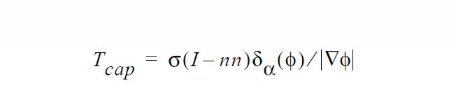
where s is the (isotropic) surface tension, I is the identity tensor, n is the vector normal to the interface and \(\zeta_a\) ( \(\phi\) ) is the smoothed Dirac delta function. The surface tension value used in this expression is obtained from the Surface Tension card found in the material file.
The actual implementation in Goma integrates the divergence term by parts so the expression that is added to the weak form of the momentum equation is:
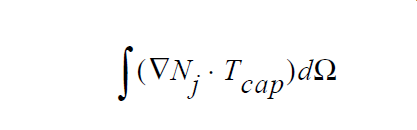
This fact introduces the issue of integration error into the problem. As obvious above, this source term involves the non-linear Dirac delta function factor. Conventional numerical integration methods often do not offer adequate accuracy in evaluating this integral, especially if if the interface width is a fraction of the average element size. This has led to introduction the level-set-specific integration methods: subelement integration and subgrid integration. In the latter case, more integration points are clustered around the interface (in essence) to improve accuracy. The integer parameter on the card should be set to zero to signify that the surface tension forces are distributed in equal measure on both sides of the interfacial curve.
In the subelement integration case, however, an actual subelement mesh is place on each of the interface-containing elements which is made to conform to the interface curve. That is, the interface curve itself is covered by these subelement boundaries. This allows the volume integral to be collapsed into a line integral and the line integral evaluated along the subelement boundaries. This, however, introduces the problem of identifying which side of the element the surface tension forces should actually be applied to. Applying them to both simultaneously while either result in a cancellation or a doubling of the surface tension effect. For these cases, the integer parameter on this card is set to a -1 or a +1 to signify that the surface tension forces are applied to the negative or positive side of the interface curve, respectively.
References#
No References.